
Medidores de Caudal de Área Variable Swagelok®
Consiga una precisión constante con los medidores de caudal de área variable Swagelok para medir el caudal de gases y líquidos. Seleccione entre las opciones de tubo metálico o de vidrio que mejor se adapten a las necesidades específicas de sus aplicaciones.
Solicite Más InformaciónSwagelok Los medidores de caudal de área variable Swagelok® utilizan un tubo cónico y un flotador para medir el caudal de líquidos y gases. Al aumentar el caudal del fluido, el flotador sube, y al disminuir el caudal, la gravedad lo hace descender. Estos medidores de caudal son fáciles de instalar, de fácil lectura y están diseñados sin piezas sometidas a desgaste, lo que reduce al mínimo la necesidad de mantenimiento. Con un ratio de reducción de 10 a 1—que permite que la medición más baja sea una décima parte de la lectura a escala real—ofrecen una medición precisa. Disponibles en escalas métricas y americanas, se adaptan a un amplio rango de aplicaciones y ubicaciones.
Cada medidor de caudal de área variable Swagelok se calibra en fábrica según el rango de caudal, el fluido y la clase de precisión especificados, utilizando aire limpio seco para los modelos de gas y agua para los modelos de líquido. También pueden calibrarse para aplicaciones específicas del usuario.
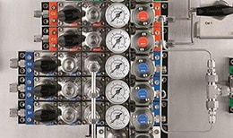
Medidores de caudal de área variable serie M (Modelos M1, M2, M4 y M4H)
Los medidores de caudal Swagelok® serie M incorporan tubos de medición metálicos para condiciones exigentes de alta temperatura o presión. Dado que con los tubos metálicos no es posible hacer lecturas directas, estos modelos incorporan visores mecánicos o electrónicos para asegurar un control claro y preciso.
Especificaciones de los modelos M1, M2, M4 y M4H
| Rango de Caudal | Aire: 5,0 a 50 hasta 18 000 a 180 000 std L/h³; 0,18 a 1,8 hasta 670 a 6700 std ft/h Agua: 0,3 a 3,0 hasta 1.000 a 10 000 L/h; 0,08 a 0,8 hasta 270 a 2.700 gal/h |
| Rangos de Temperatura | Proceso: M1 y M2: –40 a 150°C (–40 a 302°F) M4, M4H: –40 a 300°C (–40 a 572°F) Ambiente: M1 y M2: –20 a 70°C (–4 a 158°F) M4, M4H: –40 a 120°C (–40 a 248°F) |
| Máxima Presión de Entrada | Hasta 199 bar (2.888 psig) |
| Conexiones a Proceso | Accesorio roscado 1/4 a 1 1/4 pulg. NPT; Adaptador a Brida ASME 1/2 a 1 pulg. |
| Clase de Precisión | 1,6, 2,5, 4,0 |
Medidores de caudal de área variable Serie G (Modelos G1, G2, G3, G4, GM y GP)
Los modelos de la Serie G de Swagelok® utilizan tubos de medición de vidrio que permiten ver el fluido del proceso y la lectura directa del caudal.
Especificaciones de los modelos G1, G2, G3, G4, GM y GP
| Rango de Caudal | Aire: 0,5 a 5,0 hasta 500 a 5.000 std L/h³; 0,018 a 0,18 hasta 18 a 180 std ft/h Agua: 0,04 a 0,4 hasta 16 a 160 L/h; 0,065 a 0,65 hasta 4,2 a 42 gal/h |
| Rangos de Temperatura | Proceso: –5 a 100°C (23 a 212°F) Ambiente: –20 a 100°C (–4 a 212°F) |
| Máxima Presión de Entrada | Hasta 10 bar (145 psig) |
| Conexiones a Proceso | Accesorio roscado 1/4 pulg. NPT; G 1/8 (ISO 228); G 1/4 (ISO 228) |
| Clase de Precisión | 1,0, 2,5, 4,0 |
¿Necesita ayuda para seleccionar un medidor de caudal?
Catálogos de Medidores de Caudal de Área Variable
Encuentre información detallada de producto, incluidos materiales de construcción, valores nominales de presión y temperatura, opciones y accesorios.
Features: Glass and metal (armored) tube models, including miniature armored model; Highly accurate measurement even at very low flow, with individually calibrated scales based on flow tests; Flexible and adaptable to specific system requirements; High quality, durability, and repeatability; 1/8 to 1 1/4 in. process end connections

Pequeño Tamaño, Gran Impacto: Cómo Detectar y Proteger los Fallos de los Manómetros
Conozca los signos de un manómetro defectuoso y evite el riesgo para los empleados y las paradas caras para realizar reparaciones.
Cómo Prevenir los Fallos de los ManómetrosRecursos Swagelok Elaborados para Vd.
Consejos para Mantener una Muestra Representativa en un Sistema de Instrumentación Analítica
Mantener una muestra representativa en un sistema de instrumentación analítica puede ser difícil. Aprenda cómo identificar los problemas más importantes y evitar las complicaciones derivadas de una muestra de representatividad comprometida por parte de los expertos de Swagelok.
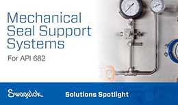
Soluciones Destacadas para Sistemas Auxiliares al Sello Mecánico
Vea cómo los sistemas auxiliares al sello mecánico Swagelok® según la norma API 682 siguen las mejores prácticas de esta norma y luego van más allá, incorporando principios de diseño que hacen que los sistemas sean fáciles de instalar y de mantener.

Cómo la Fabricación de Sistemas de Fluidos puede Aliviar la Escasez de Recursos
Hay muchos sistemas de fluidos comunes de los que dependen las operaciones de planta, y elegir el proveedor de fabricación adecuado puede ser muy beneficioso si Vd. tiene escasez de recursos.

Medición de Proceso — Mejores Prácticas en las Líneas de Impulso
Puede ser difícil encontrar problemas en la aplicación de instrumentación de proceso si solo se tiene en cuenta el transmisor. Aprenda cómo solucionar problemas en la línea de instrumentación de proceso gracias a los consejos y mejores prácticas de Swagelok.