|
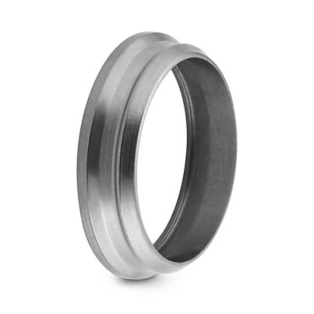
316 Stainless Steel Back Ferrule for 14 mm Swagelok Tube Fitting
Part #: SS-14M4-1
|
||||||||||||||||||||||||||||||||
|---|---|---|---|---|---|---|---|---|---|---|---|---|---|---|---|---|---|---|---|---|---|---|---|---|---|---|---|---|---|---|---|---|
Specifications
バック・フェルールバック・フェルールにより、チューブを漏れなく確実にグリップ可能ー液体およびガス・システムにおける重要なシール性の維持に適しています。 Log in or Register to view price お問い合わせ本製品に関するご質問は、担当のスウェージロック指定販売会社までお問い合わせください。指定販売会社は、投資を最大限に活用するためのアドバイスも提供いたします。
安全な製品の選定について:
システム設計者およびユーザーは、製品カタログの内容をすべてご覧になった上で、安全な製品の選定を行ってください。 安全にトラブルなく機能するよう、システム全体の設計を考慮して、製品をご選定ください。 機能、材質の適合性、数値データなどを考慮し製品を選定すること、また、適切な取り付け、操作およびメンテナンスを行うのは、システム設計者およびユーザーの責任ですので、十分にご注意ください。 Warning: Do not mix/interchange Swagelok products or components not governed by industrial design standards, including Swagelok tube fitting end connections, with those of other manufacturers. |
システム設計者およびユーザーは、製品カタログの内容をすべてご覧になった上で、安全な製品の選定を行ってください。 安全にトラブルなく機能するよう、システム全体の設計を考慮して、製品をご選定ください。 機能、材質の適合性、数値データなどを考慮し製品を選定すること、また、適切な取り付け、操作およびメンテナンスを行うのは、システム設計者およびユーザーの責任ですので、十分にご注意ください。
Warning: Do not mix/interchange Swagelok products or components not governed by industrial design standards, including Swagelok tube fitting end connections, with those of other manufacturers.
316 Stainless Steel Back Ferrule for 14 mm Swagelok Tube Fitting
Log in or Register to view price
Catalogs
バック・フェルール
Swagelok® tube fittings and tube adapters reduce the risk of costly system downtime with reliable tubing connections and are available in a variety of sizes and materials.
Swagelok's Snoop liquid leak detector exposes gas leaks while pipe thread sealants SWAK, PTFE and PTFE-free tape and thread lubricant Goop can help prevent future leaks.
Features: Step-by-step identification procedure for threads and end connections.
Find information about tubing selection, handling, and installation as well as suggested allowable working pressure tables with elevated temperature factors for several metal alloys.
This document specifies guidelines used by Swagelok® Company and its suppliers to ensure compliance with product cleanliness requirements as stated in ASTM G93 Level C. Application of the document is limited to wetted system components. This document must be used in conjunction with product catalogs, technical bulletins, and reports.
Swagelok® Specification SC-10 defines the cleaning, lubrication, assembly, and packaging requirements for standard Swagelok products and describes practices used to meet these requirements.
Specifications
SS-14M4-1 — 316 Stainless Steel Back Ferrule for 14 mm Swagelok Tube Fitting
| Attribute | Value |
|---|---|
| ボディ材質 | 316 Stainless Steel |
| 洗浄プロセス | Standard Cleaning and Packaging (SC-10) |
| コネクション1 サイズ | 14 mm |
| 流量制限 | いいえ |
| eClass (4.1) | 37020718 |
| eClass (5.1.4) | 37020590 |
| eClass (6.0) | 21022110 |
| eClass (6.1) | 37020590 |
| eClass (10.1) | 37020590 |
| UNSPSC (4.03) | 27121703 |
| UNSPSC (10.0) | 31181503 |
| UNSPSC (11.0501) | 31181503 |
| UNSPSC (13.0601) | 31401700 |
| UNSPSC (15.1) | 31401700 |
| UNSPSC (17.1001) | 31163102 |
Resources
Drawings
Two-dimensional renderings are available for this product. Download the CAD file.
Three-dimensional renderings are available for this product. Download the CAD file.
Sales drawings are available for this product. Download the files.
Similar Products
|
Part #
|
Body Material
|
Connection 1 Size
|
Connection 1 Type
|
Connection 2 Size
|
Connection 2 Type
|
|
|---|---|---|---|---|---|---|
| 6ML-1214-1A | 6 Moly | 3/4 in. | - | - | - | View Product |
| 6ML-404-1A | 6 Moly | 1/4 in. | - | - | - | View Product |
| 6ML-604-1A | 6 Moly | 3/8인치 | - | - | - | View Product |
| 6ML-814-1A | 6 Moly | 1/2인치 | - | - | - | View Product |
| 6MO-814-1A | 6 Moly | 1/2인치 | - | - | - | View Product |
| 825-404-1 | 합금 825 | 1/4인치 | - | - | - | View Product |
| B-204-1 | 황동 | 1/8인치 | - | - | - | View Product |
| B-404-1 | 황동 | 1/4인치 | - | - | - | View Product |
| HC-204-1 | 합금 C-276 | 1/8인치 | - | - | - | View Product |
| HC-404-1 | 합금 C-276 | 1/4인치 | - | - | - | View Product |
| HC-604-1 | 합금 C-276 | 3/8인치 | - | - | - | View Product |
| HC-814-1 | 합금 C-276 | 1/2인치 | - | - | - | View Product |
| INC-404-1 | 합금 600 | 1/4인치 | - | - | - | View Product |
| M-604-1 | 합금 400/R-405 | 3/8인치 | - | - | - | View Product |
| M-814-1 | 합금 400/R-405 | 1/2인치 | - | - | - | View Product |
| NY-1214-1 | 나일론 | 3/4인치 | - | - | - | View Product |
| NY-1614-1 | 나일론 | 1인치 | - | - | - | View Product |
| NY-404-1 | 나일론 | 1/4인치 | - | - | - | View Product |
| NY-604-1 | 나일론 | 3/8인치 | - | - | - | View Product |
| NY-814-1 | 나일론 | 1/2인치 | - | - | - | View Product |
| PFA-424-1 | PFA | 1/4인치 | - | - | - | View Product |
| PFA-824-1 | PFA | 1/2인치 | - | - | - | View Product |
| SS-1014-1 | 316 스테인리스강 | 5/8인치 | - | - | - | View Product |
| SS-104-1 | 316 스테인리스강 | 1/16인치 | - | - | - | View Product |
| SS-104-1-B1000 | 316 스테인리스강 | 1/16인치 | - | - | - | View Product |
| SS-10M4-1 | 316 스테인리스강 | 10mm | - | - | - | View Product |
| SS-1214-1 | 316 스테인리스강 | 3/4인치 | - | - | - | View Product |
| SS-12M4-1 | 316 스테인리스강 | 12mm | - | - | - | View Product |
| SS-1414-1 | 316 스테인리스강 | 7/8인치 | - | - | - | View Product |
| SS-15M4-1 | 316 스테인리스강 | 15mm | - | - | - | View Product |
| SS-1614-1 | 316 스테인리스강 | 1인치 | - | - | - | View Product |
| SS-16M4-1 | 316 스테인리스강 | 16mm | - | - | - | View Product |
| SS-18M4-1 | 316 스테인리스강 | 18mm | - | - | - | View Product |
| SS-2004-1 | 316 스테인리스강 | 1 1/4인치 | - | - | - | View Product |
| SS-204-1 | 316 스테인리스강 | 1/8인치 | - | - | - | View Product |
| SS-20M4-1 | 316 스테인리스강 | 20mm | - | - | - | View Product |
| SS-22M4-1 | 316 스테인리스강 | 22mm | - | - | - | View Product |
| SS-2404-1 | 316 스테인리스강 | 1 1/2인치 | - | - | - | View Product |
| SS-25M4-1 | Acier inoxydable 316 | 25 mm | - | - | - | View Product |
| SS-28M4-1 | Acier inoxydable 316 | 28 mm | - | - | - | View Product |
| SS-2M4-1 | 316 ステンレス鋼 | 2 mm | - | - | - | View Product |
| SS-304-1 | 316 ステンレス鋼 | 3/16 インチ | - | - | - | View Product |
| SS-3204-1 | 316 ステンレス鋼 | 2 インチ | - | - | - | View Product |
| SS-3M4-1 | 316 ステンレス鋼 | 3 mm | - | - | - | View Product |
| SS-404-1 | 316 ステンレス鋼 | 1/4 インチ | - | - | - | View Product |
| SS-404-1BQ | 316 ステンレス鋼 | 1/4 インチ | - | - | - | View Product |
| SS-4M4-1 | 316 ステンレス鋼 | 4 mm | - | - | - | View Product |
| SS-604-1 | 316 ステンレス鋼 | 3/8 インチ | - | - | - | View Product |
| SS-6M4-1 | 316 ステンレス鋼 | 6 mm | - | - | - | View Product |
| SS-814-1 | 316 ステンレス鋼 | 1/2 インチ | - | - | - | View Product |
| SS-8M4-1 | 316 ステンレス鋼 | 8 mm | - | - | - | View Product |
| T-1214-1 | PTFE | 3/4 インチ | - | - | - | View Product |
| T-12M4-1 | PTFE | 12 mm | - | - | - | View Product |
| T-15M4-1 | PTFE | 15 mm | - | - | - | View Product |
| T-1614-1 | PTFE | 1 インチ | - | - | - | View Product |
| T-304-1 | PTFE | 3/16 インチ | - | - | - | View Product |
| T-3M4-1 | PTFE | 3 mm | - | - | - | View Product |
| T-404-1 | PTFE | 1/4 インチ | - | - | - | View Product |
| T-504-1 | PTFE | 5/16 インチ | - | - | - | View Product |
| T-6M4-1 | PTFE | 6 mm | - | - | - | View Product |
| T-814-1 | PTFE | 1/2 インチ | - | - | - | View Product |
| T-8M4-1 | PTFE | 8 mm | - | - | - | View Product |
Contact
If you have questions about this product, please contact your local authorized sales and service center. They can also tell you about supporting services to help you get the most out of your investment.