

Swagelok®逆止弁/エクセス・フロー・バルブ(過流防止弁)
Swagelok逆止弁を使用すると、一般的なアプリケーションや高純度アプリケーションにおいて逆方向の流れを制御することができます。クラッキング圧力調節可能型またはクラッキング圧力固定型を選ぶことができます。また、Swagelokエクセス・フロー・バルブ(過流防止弁)は、バイパス機構を排除することで、システムの整合性や安全性を高めています。
逆止弁 | 流体の流れを一定方向に維持します。
エクセス・フロー・バルブ(過流防止弁) | 二次側での流体の過剰流出を防止します。
Swagelok®逆止弁を使用すると、流体の流れを一定方向に維持することができます。Swagelok逆止弁は、ポペット式、リフト式、溶接式などさまざまなタイプがあり、中圧/高圧の一般的なアプリケーションや高純度 アプリケーションに使用することができます。
Swagelok逆止弁は、さまざまなエンド・コネクションやシール材質を選ぶことができるため、ユーザーのシステムやプロセス流体に適した、容易に統合可能なソリューションを見つけることができます。一部のSwagelok逆止弁には溶接式デザインを採用しているため、高純度アプリケーションにおいてシステム流体を確実に封止することができます。また、Oリングを使用していない超高純度用フルオロポリマー・ポペット式逆止弁を使用すると、流れを最大限化すると同時に差圧を低減し、たまり部分を排除し、漏れの無い優れたシール性能を実現することができます。
Swagelok®エクセス・フロー・バルブ(過流防止弁) XSシリーズは、バルブの二次側で流れが過剰になるとスロット・ポペットがトリップ位置に移動し、システム流体の過剰流出を阻止します。その後、一次側と二次側の圧力が均等になるとポペットがリセットされます。エクセス・フロー・バルブを使用すると、複雑なバイパス機構が不要になり、メンテナンス時間を削減することができます。
クラッキング圧力と再シール圧力との違いを理解し、逆止弁が適切に機能しているか確認しましょう。
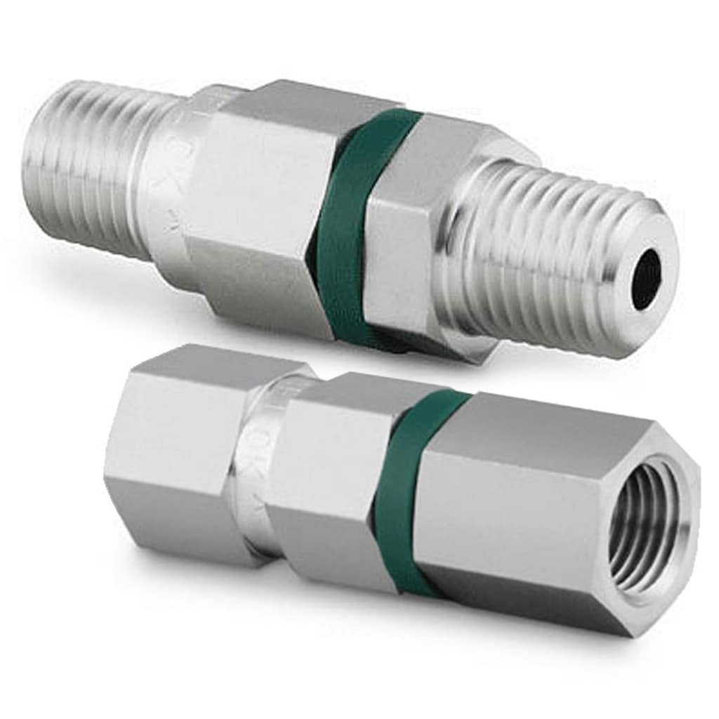
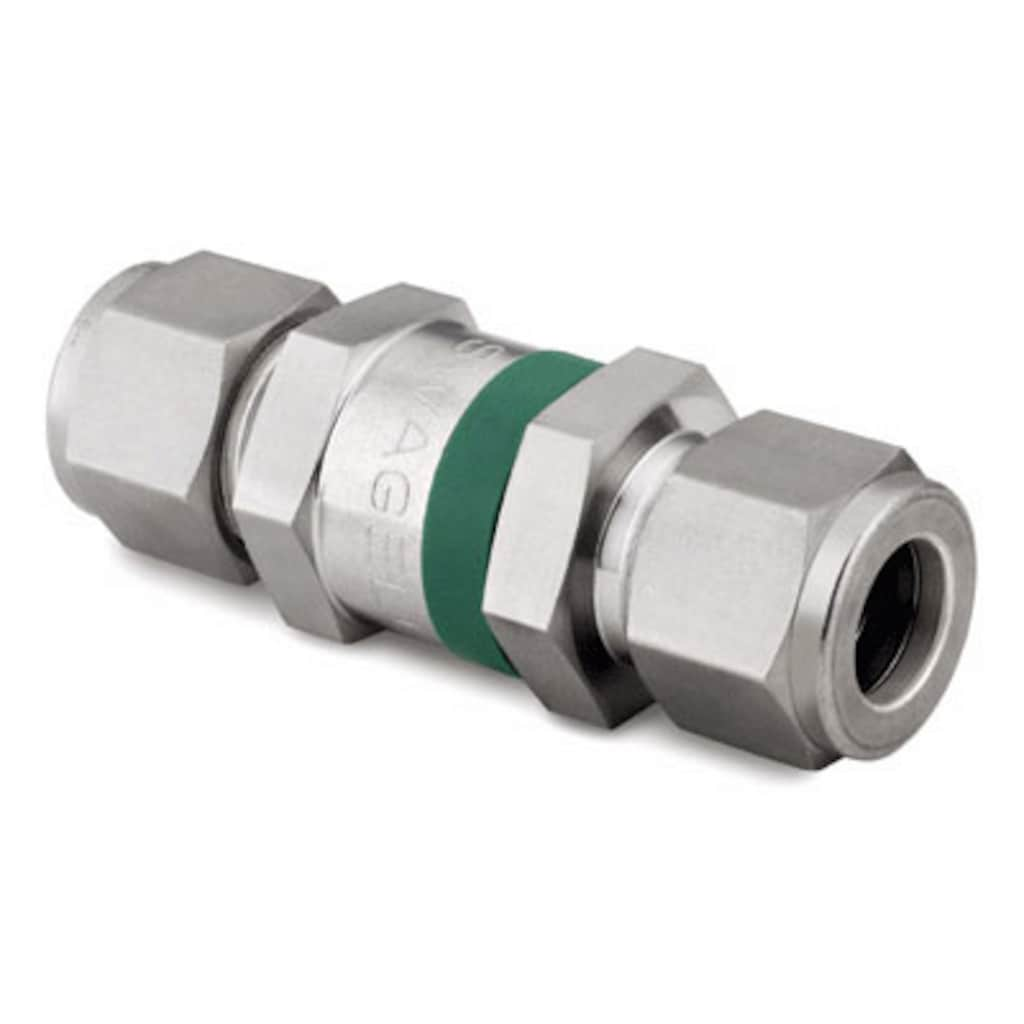
逆止弁のカテゴリー
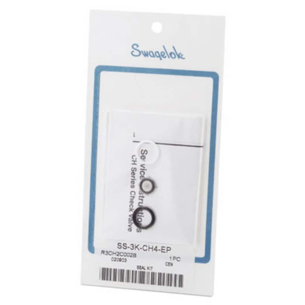
スペアー・パーツ/アクセサリー
ポペット式逆止弁のメンテナンス用の交換用部品/アクセサリーとして、デフレクター・キャップやメンテナンス用アクセサリー(スプリング・キット、シール・キット、ポペット交換キットなど)を幅広く取り揃えています。
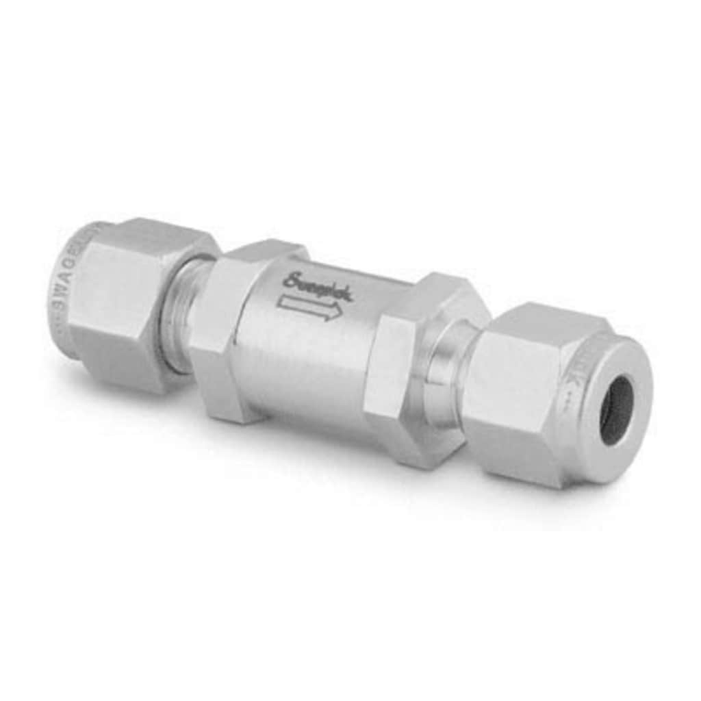
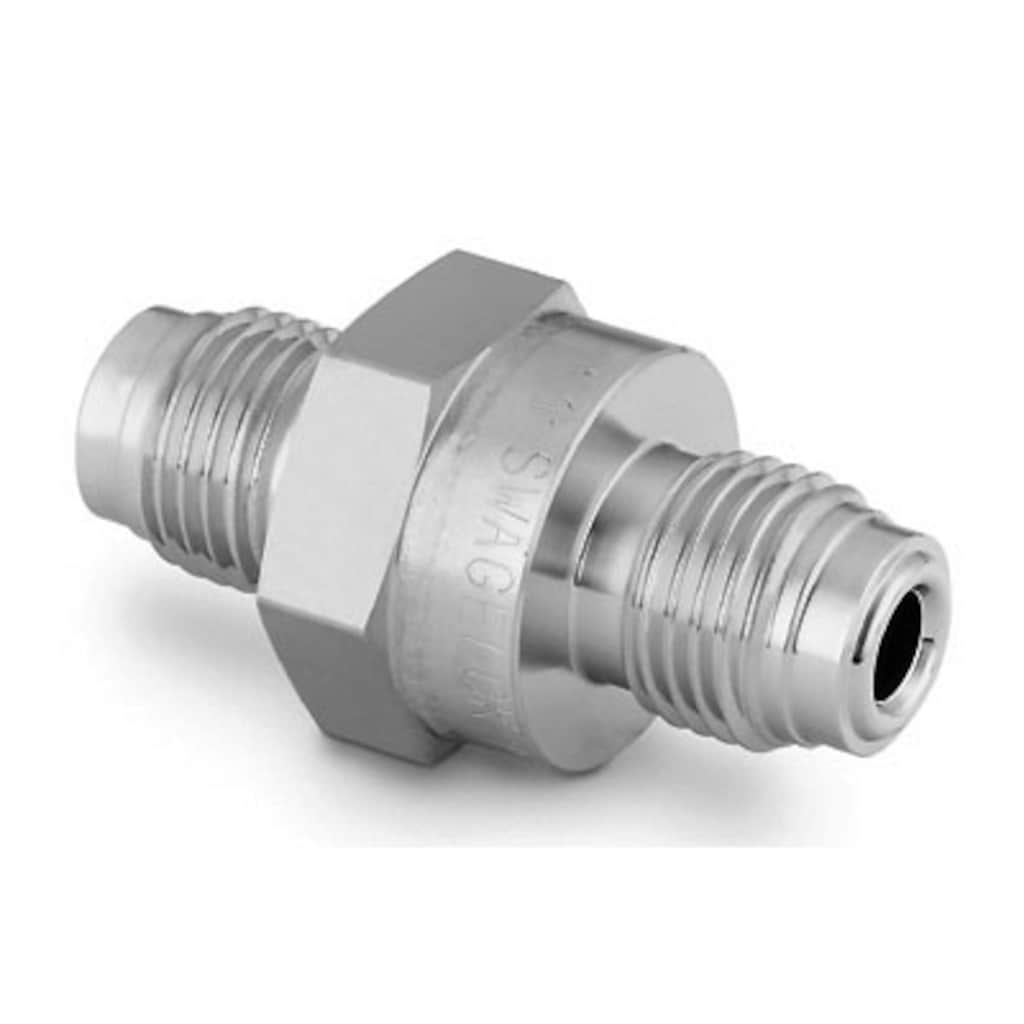
ポペット式逆止弁、C / CP / CH シリーズ
ポペット式逆止弁(材質:ステンレス鋼または真ちゅう)は、さまざまなエンド・コネクション、そしてクラッキング圧力固定型またはクラッキング圧力調節可能型を選ぶことができます。
逆止弁のカタログ
構成部品とその材質、使用圧力、使用温度、オプション、アクセサリーなど、製品に関する詳細情報につきましては、以下の資料をご参照ください。
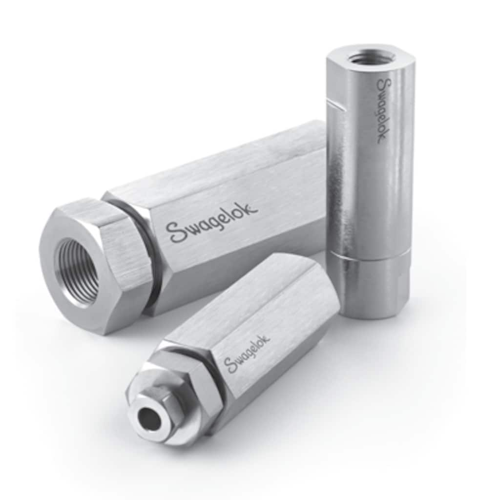
Features: Working pressures up to 6000 psig (413 bar); Adjustable and fixed cracking pressures Variety of end connections; 316 stainless steel and brass materials
Swagelok® offers medium- and high-pressure fittings, tubing, valves, and related accessories with temperatures up 1000°F (537°C), pressure ratings up to 60 000 psig (4134 bar) in sizes ranging from 1/4 to to 1 in. for medium-pressure products and 1/4 to 9/16 in. for high-pressure products. NACE® MR0175/ISO15156 compliance is available.
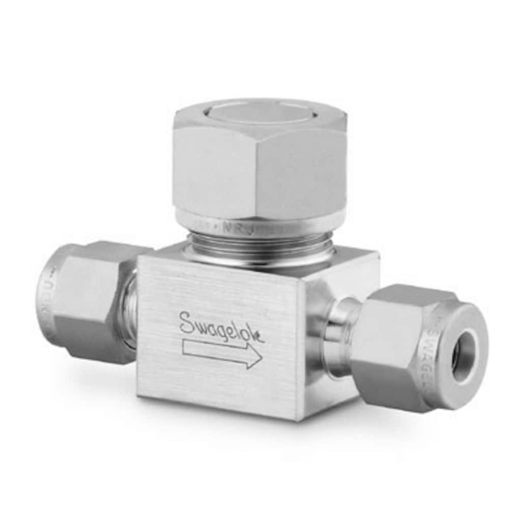
Features: All-welded design provides reliable containment of system fluid; Forward flow starts at less than 2 psig (0.14 bar) pressure differential; Valve closes with less than 2 psig (0.14 bar) back pressure; 316L SS body offers enhanced material purity
Features: Alloy 625, alloy 825, and Alloy 2507 super duplex stainless steel materials; Available for CH4 adn Ch8 series check valves; Working pressures up to 6 000 psig (413 bar); 1/4 to 1/2 in. Swagelok tube fitting or NPT end connections; Fixed cracking pressures: 1 to 25 psi (0.07 to 1.8 bar)
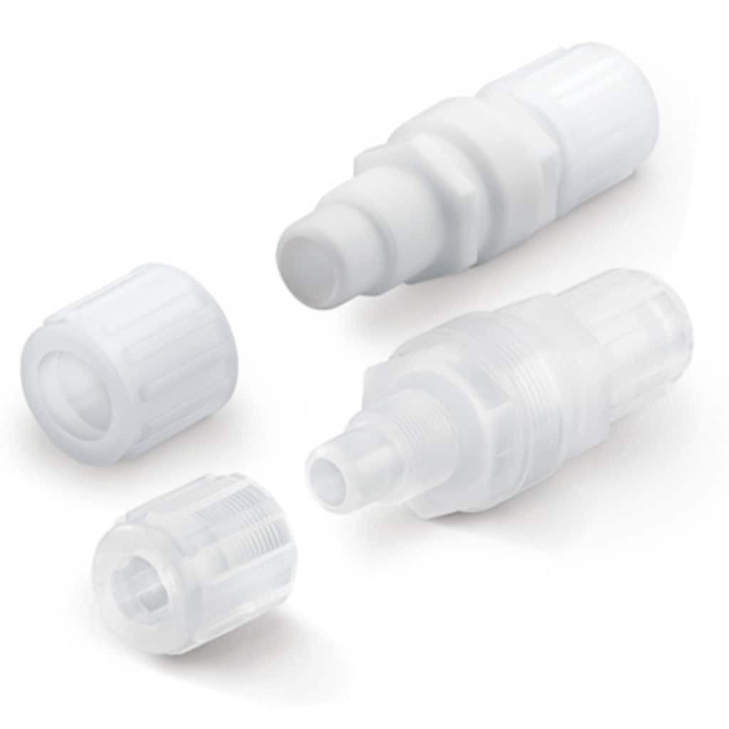
Features: Modified PTFE wetted components meet SEMI Standard F57-0301 for ultrahigh-purity system components; Fine thread flare and Nippon Pillar® Super 300 end connections; Low cracking and reseal pressure
Rugged, all-stainless steel construction; Reverse flow coefficient less than 0.1 % of forward flow coefficient; No springs or elastomers; Compact size
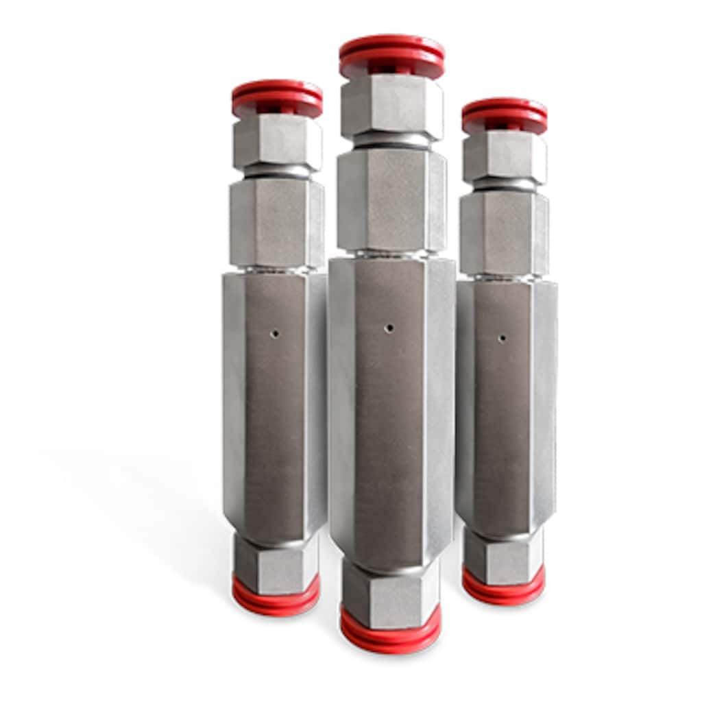
Stop uncontrolled release of system media if downstream line ruptures. Features: Pressures up to 6000 psig (413 bar); Temperatures up to 400°F (204°C); 1/8 to 1/2 in. and 6 to 12 mm end connections; Stainless steel construction
Calculer le débit pour bien choisir une vanne
Utilisez notre calculateur de coefficient de débit (Cv) pour choisir une vanne d’une taille adaptée à vos besoins.
Utiliser l’outil関連資料/コラム記事

Comment choisir des vannes adaptées à un système fluide industriel
Découvrez comment choisir des vannes adaptées à vos systèmes fluides ou d’échantillonnage en suivant la méthode STAMPED.

Minimize the Costs of Fugitive Emissions with Low-E Valves
Fugitive emissions are a growing concern in the chemical and petroleum refining industry. Certified low-emissions (Low-E) valves can protect your facility and bottom line. Learn what they are, how they are tested, and how they can help you in this post.
How Shenyang Blower Works Group Improved Safety and Reliability
Learn how Swagelok Shanghai has helped Shenyang Blower Works Group Corporation achieve consistency, reliability, and cost savings for its customers while improving its own safety and production efficiency.

Améliorer un programme de maintenance en étiquetant les vannes et les flexibles
Découvrez ce que deux spécialistes de Swagelok ont à dire sur la façon dont un système d’étiquetage rigoureux des flexibles et des vannes dans l’ensemble de vos systèmes fluides industriels peut vous aider à simplifier la maintenance et limiter les immobilisations de ces systèmes.